Drumulator 8-fold Sound Expansion to DIY
by mLab.midisoft.de
The sound sets are selected with the drumulator buttons 1-8 & ENTER.
Therefore no drilling or additional switches are required.
Die Auswahl der Soundsets erfolgt über die Drumulator-Tasten 1-8 & ENTER.
Daher sind keine Bohrungen oder zusätzliche Schalter erforderlich.

To switch through the 8 sound sets, (MOVIE)
Hold down one of the 8 number buttons and press ENTER.
The following sound sets are available.
-
E-MU Drumulator Factory Sound Set
-
Digi-Drums N101 Electronic Drums 1
-
Digi-Drums N102 Electronic Drums 2
-
Digi-Drums N103 Latin Percussion
-
Digi-Drums N104 African/Misc. Percussion
-
Digi-Drums N105 Rock Kit
-
Digi-Drums N106 Analog Drum Machine
-
Digi-Drums N107 Jazz Drums
| Here's a pdf file to download and print out (please do not scale) | |
|---|---|
| stick it beneath the numbers 1 ... 8 | |
Assembly of the circuit boards |
Schematics & Boards |
Unfortunately, the fully assembled kit is no longer available. € 50, - including free shipping within the EU |
|
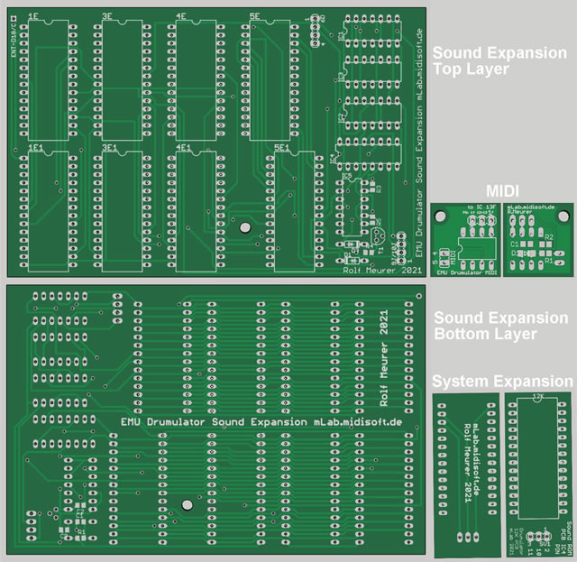
Sound Expansion board |
||||
| Qty | Parts | Package | Description | Value |
| 4 | 1E,3E,4E,5E | DIL28 Socket | CMOS EPROM | 27C512 |
| 4 | 1E1,3E1,4E1,5E1 | DIL28 Socket | CMOS EPROM | 27C512 |
| 1 | ENTER-BUTTON | Wire Pad | 1-Way Through-Hole | to Drumulator D18 Cathode |
| 1 | SV1 | Male Header | 3-Way | to 12k Sytem ROM board |
| 2 | 6D | Male Header | 4-Way | to Drumulator IC 6D |
| 2 | 9J/10J | Male Header | 4-Way | to Drumulator IC 9J and 10J |
| 2 | C1, C2, C3 | Capacitor | SMD 0805 | 22n |
| 1 | C3 | Capacitor | SMD 0805 | 100n |
| 2 | D1, D3 | Diode | Through-Hole | 1N4148 |
| 2 | IC1, IC2 | DIL14Socket | Quad 2-input OR | 74LS32N |
| 1 | IC3 | DIL14 Socket | Hex Inverter | 74LS14N |
| 1 | IC4 | DIL16 Socket | Quad D Latch | 4042N |
| 1 | IC5 | DIL14 Socket | Quad 2-in NAND | 74LS00N |
| 2 | R1, R4 | Resistor | SMD 0805 | 82k |
| 2 | R3, R5 | Resistor | SMD 0805 | 10k |
| 1 | T1 | Transistor | NPN (B-C-E) | 2N5172 |
System Expansion board |
||||
| 1 | 12K | DIL28 Socket | CMOS EPROM | 27C512 |
| 1 | SV1 | Male Header | 3-Way | to Sound Expansion board |
MIDI board |
||||
| 1 | MIDI | DIL08 Socket | Opto Coupler | 6N138 or 6N139 |
| 1 | SV1 | Male Header | 3-Way | to Drumulator IC 13F |
| 1 | JP1 | Male Header | 2-Way | to MIDI Jack |
| 1 | D1 | Diode | Through-Hole | 1N4148 |
| 1 | C1 | Capactor | SMD 0805 | 100n |
| 1 | R1 | Resistor | SMD 0805 | 220 Ohm |
| 1 | R2 | Resistor | SMD 0805 | 1k |
Wiring & mounting |
The Sound Expansion board |
1. Wiring |
| Header name = 6D Pin1 to EMU IC-6D pin3 Pin2 to EMU IC-6D pin4 Pin3 to EMU IC-6D pin5 Pin4 to EMU IC-6D pin6 Header name = 9J/10J |
2. Mounting |
| The expansion ROM board chip socket 5E has a Long Pin header (straight forwards except PIN 1, 27, 20, 22) Plug this header into the EMU IC socket 5E and fix the board with an UNC4-40 spacer under the appropriate mounting hole. |
The System ROM board |
1. Wiring |
| Header name = SV1 Pin1 to Sound Expansion IC-4 pin2 Pin2 to Sound Expansion IC-4 pin10 Pin3 to Sound Expansion IC-4 pin11 |
2. Mounting |
| The system ROM board chip socket 12K has a Long Pin header (straight forwards except PIN 1, 26, 27) Just plug this header into the EMU IC socket 12K |
The MIDI IN board |
if your Drumulator has no MIDI IN yet, the System ROM supports MIDI IN for all 8 sound sets. |
1. Wiring |
Header name = to IC 13F Header name = MIDI |
2. Mounting |
Fix the MIDI board through the mounting hole with an UNC4-40 spacer near by EMU IC-13F |
3. Using |
To set a MIDI In channel (1 ... 16) To activate the MIDI IN Mode To leave the MIDI IN Mode PRESS ENTER |
The ROMs |
9 x 27C512[64k] |
Download |
| Each of the 2 Sound ROM sets (1E, 3E, 4E, 5E) & (1E1, 3E1, 4E1, 5E1) contains 4 Drumulator sound sets. The Sytem ROM (12k) contains individual operating data for all 8 sound sets |
||
Sound ROM-Set 1 |
(Electric 1, Analog, Latin, Jazz) | |
| 1E.bin | Sound ROM | (2F32) Checksum |
| 3E.bin | Sound ROM | (7B4F) Checksum |
| 4E.bin | Sound ROM | (96A2) Checksum |
| 5E.bin | Sound ROM | (CE2C) Checksum |
Sound ROM-Set 2 |
(African, Rock, Electric 2, Factory) | |
| 1E1.bin | Sound ROM | (5BDF) Checksum |
| 3E1.bin | Sound ROM | (5694) Checksum |
| 4E1.bin | Sound ROM | (8BD0) Checksum |
| 5E1.bin | Sound ROM | (1957) Checksum |
Sytem ROM |
(12k) | |
| 12k_MIDI.bin | System ROM | (7F40) Checksum |
ROM address assignment |
||
Name |
Sound ROM addr |
System ROM addr |
| [ROM Set 1] | 1E,3E,4E,5E | [12K] |
| Electronic 1 | 0000-3FFF | 0000-1FFF |
| Analog | 4000-7FFF | 2000-3FFF |
| Latin | 8000-BFFF | 4000-5FFF |
| Jazz | C000-FFFF | 6000-7FFF |
| [ROM Set 2] | 1E1,3E1,4E1,5E1 | |
| African | 0000-3FFF | 8000-9FFF |
| Rock | 4000-7FFF | A000-BFFF |
| Electronic 2 | 8000-BFFF | C000-DFFF |
| Factory | C000-FFFF | E000-FFFF |