CEREBEL USB MIDI HOST – Identified Design Errors
MCU Clock Frequency: The MCU operates at 8 MHz, whereas the required frequency is 16 MHz.
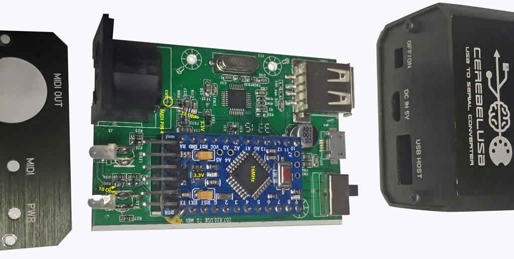
Incorrect MIDI Output Circuit:
MIDI Pin 4 is connected to +5 V through a 220 Ω resistor.
MIDI Pin 5 is connected to 3.3 V through a 220 Ω resistor.
This configuration is invalid because:
a. A 5 V pull-up on Pin 4 cannot be combined with a 3.3 V signal on Pin 5.
b. Both voltages must be equal to ensure proper operation of the receiving MIDI device.
Otherwise, the optocoupler LED will remain continuously active (anode at 5 V, cathode at 3.3 V).
Recommended Corrections (by R. Meurer, midisoft.de):
Replace the MCU with a 16 MHz / 3.3 V version, or alternatively use a 16 MHz / 5 V MCU together with a 3.3 V voltage regulator.
Isolate MIDI Pin 4 and insert a 33 Ω resistor between MIDI Pin 4 and 3.3 V.
Replace the series resistor on MIDI Pin 5: change from 220 Ω to 10 Ω.
Update the device with the latest firmware (USB MIDI HOST by Yuuichi Akagawato).
CEREBEL USB MIDI HOST – Hardware Issues & Fixes
The MCU runs at only 8 MHz — it should be 16 MHz.
MIDI OUT is wired incorrectly:
Pin 4 has +5 V via 220 Ω.
Pin 5 has 3.3 V via 220 Ω.
This mix of 5 V and 3.3 V doesn’t work. Both lines must be at the same voltage, otherwise the optocoupler in the receiving device is always on (5 V on anode, 3.3 V on cathode).
Use a 16 MHz / 3.3 V MCU. Alternatively, use a 16 MHz / 5 V MCU and swap the regulator to 3.3 V.
Cut the trace to Pin 4 and add a 33 Ω resistor between Pin 4 and 3.3 V.
Change the resistor on Pin 5 from 220 Ω to 10 Ω.
Flash the latest firmware (USB MIDI HOST by Yuuichi Akagawato).